Preface: For explanation of VLAN tagging, see this post.
This seems quite a common thing to do yet it’s proved to be a huge ball-ache with DD-WRT. Here’s the result of many days of faffing about attempting to get this working.
The usecase is thus… We have an established wifi network comprising of D-Link DIR-615 access points flashed with DD-WRT, a router running pfSense and a managed Gigabit switch supporting 802.1Q VLAN tagging. It was required to have a second wifi network for guests of the office to get online. The guest wifi had to be separate from the main wifi in such that the main network was secure from intrusion, guests should be sent to the company website when they log in and we didn’t want to have to double up the access points or run more structured cabling to connect them.
To cut a long story short, the D-Link DIR-615 didn’t work out. This is because only Broadcom based hardware supports hardware VLAN tagging on DD-WRT and the DD-WRT software VLAN tagging just plain doesn’t work – even on Broadcom based hardware. I ended up, after days of faffing, buying some Linksys E1000 and flashing them with DD-WRT myself. Any of the devices listed here that support 802.1Q VLAN tagging should be fine.
The start point was easy. On pfSense, under Interfaces -> (assign) -> VLANs, I created 2 VLANs on the interface that is the LAN. In my case, sk1. These were tagged 1 (primary LAN VLAN ID) and 4 (guest LAN VLAN ID).

This created 2 new “Network ports” under Interfaces -> (assign) -> Interface assignments called “VLAN1 on sk1” and “VLAN4 on sk1”. VLAN1 was assigned to the existing LAN interface, in place of sk1, and I added another interface called “GuestNet” and assigned VLAN4 to this.
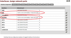
On setting up the switch to tag the port that the pfSense interface was connected to, into VLANs 1 and 4, the router worked as expected.
I set up a static IP address on the GuestNet interface and also set up DHCP to issue IP addresses. I initially added an “allow all” firewall rule to the interface and enabled Captive Portal. Finally, I set up outbound NAT so this interface could access the Internet. Our remote server firewall rules permit traffic from our primary NAT IP so I NAT’ed to an alternative public IP for added security. I won’t go into the details of these – they’re all fairly self explanatory. Drop me a comment to this post if you’re stuck with any of this.
I tested the Captive Portal setup by hooking a laptop up to a port on the switch which was set to untagged VLAN 4. This got an IP address from DHCP and was forced to authorize through Captive Portal before getting onto the network.
Now the bit that took me a long time to figure out – DD-WRT. The first step, which works great, is to add a second wifi network. This is done as a Virtual Interface under Wireless -> Basic Settings.
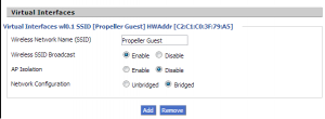
Assign security to this, if you require. If you’re using Captive Portal, this shouldn’t be needed.
Next, you’ll need to break this away from the primary bridge. To do this, under Setup -> Networking, create a new bridge called br1 and click “Apply Settings”. Assign the guest wifi interface that DD-WRT created to this bridge. This will typically be called wl0.1 on Broadcom devices. All being well, you shouldn’t be able to connect to guest Wifi but you should be able to connect to the private wifi.
Now we have to jump into Telnet to VLAN tag ports. Apparently, on some devices, this is possible via the Setup -> VLANs web interface but support is seemingly very flaky. There’s some great docs on doing this via Telnet on the wiki. It seems the best support is on the LAN ports and much of the time you cannot VLAN tag the WAN port.
First look at the existing LAN VLAN (often VLAN1) and see how it’s setup.
root@Propeller Communications 1:~# nvram show | grep vlan1ports
vlan1ports=1 2 3 4 5*
You can see which VLAN is the LAN one from br0 on the Setup -> Networking page. It’ll always be the lowest numbered VLAN of the two in the bridge. So if you have vlan1 and vlan2 bridged, vlan1 is the LAN. If you have vlan0 and vlan1 bridged, vlan0 is the LAN.
You’ll see here that this VLAN has ports 1-4 (all the LAN ports) as well as 5*. The 5 is the router’s internal CPU and must be in all VLANs; apparently this is 8 on Gigabit routers. The * signifies that this is the default VLAN for untagged packets and should only be on one VLAN (this doesn’t work on some hardware, like the E1000). Port 0 is typically the WAN interface – as I said, this often can’t be tagged. To tag ports, you simply suffix the port number with a t. Thus, to assign port 1 tagged to VLAN1 and VLAN4, we’d do this:
nvram set vlan1ports=”1t 2 3 4 5*”
nvram set vlan4ports=”1t 5″
nvram set port1vlans=”1 4″
nvram set vlan4hwname=et0
nvram commit
reboot
This should hopefully be self explanatory. The vlan4hwname activates VLAN4.
Be sure to tag the port on your switch into the appropriate VLANs.
NOTE: On some routers (E1000 included), the ports are labeled backwards. If it doesn’t work as intended when you plug the network into Port1, try plugging into Port4. What I did was to untag the port on the switch and ping the DD-WRT device. I then swapped the network cable between the LAN ports until the ping didn’t work, even after waiting a few moments. I enabled tagging on the switch port and the pinging started up.
Once the device has rebooted, you should be able to assign vlan4 to br1 under Setup -> Networking.
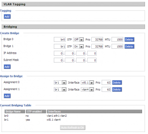
All being well, your guest wifi network should start working from the DHCP server on VLAN4.
Finally, I removed the temporary “Allow All” rules on the pfSense firewall for this and replaced them with a rule to allow ICMP echo requests to the GuestNet interface, a block of all IPv4 traffic to private networks (via an alias called PrivateNets), a block of all IPv6 traffic and finally an allow of everything else. This means guest devices cannot access any private networks by IP address, including their own, but can access the Internet.
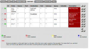
And that’s it. A bit of a balls but great when you get it right. Comment if you have any Qs.
Looking at their Trac timeline it seems DD-WRT is very actively developed – I wonder if a lot of these issues (e.g. the VLAN page) are fixed in a later revision. You can download newer builds from the FTP site.
Hmmm, yeh – this looks like the latest stable build. Didn’t want to brick the AP – looks like a mess of soldering and serial cables to get it back.
Could be worth seeing if the latest firmware fixes software tagging on the DIR-615s. Worst case, it’ll be bricked and go in the bin… rather than sit in the cupboard for 3 years and then go in the bin 😛
I’m interested in how you setup the Outbound NAT for internet access? I have setup a near identical configuration but cannot get internet access on the guest WiFi network.
I’ve configured NAT on pfSense to use “Manual Outbound NAT rule generation”. There’s then 2 rules added – one for primary and one for guest. Screenshot is below. You’ll see we NAT the traffic out of different IP addresses to ensure that problems (e.g. copyright infringement reports from movie companies) are easily traced to the relevant network.
https://phil.lavin.me.uk/downloads/nat.png
Excellent, that worked thanks! Is there also a way to resolve internal websites/services using this method so that DNS traffic can go out from the WAN and back to pfsense as such? Web access etc are all working apart from resolving our externally facing websites and Exchange HTTPS/ActiveSync which has me thinking there’s an outbound DNS issue somewhere.