The inspiration for this project came from @nivnov pointing me to http://wallbox.weebly.com/. I had somewhat of a different take on the circuitry and software than it’s author, Steve Devlin. The pulse train of my Wallbox was also different. This is all explained below.
The Wallbox
A wallbox is a device dating from circa 1950s USA. It was placed on tables in diners to increase revenue from Jukeboxes. It contains no music, nor does it have a speaker. It could be considered a remote control for the diner’s main Jukebox.
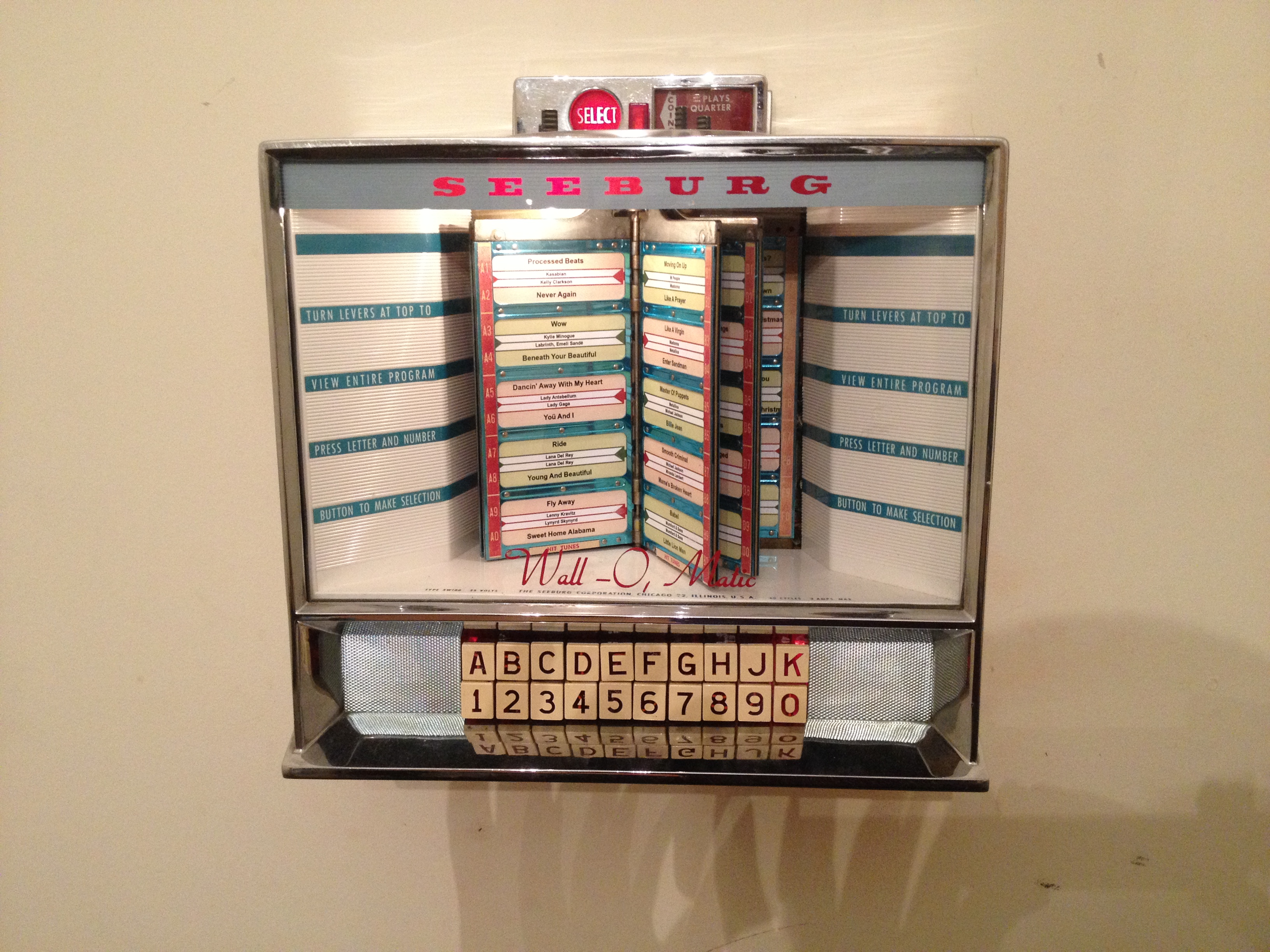
I opted for a Seeburg Wall-O-Matic 100 Type 3W100. Wallboxes will be heavily mechanical with very basic circuitry. They will function such that a key combination will be output as a train of electrical pulses caused by an arm rotating over a set of electrical contacts.

Powering the Wallbox
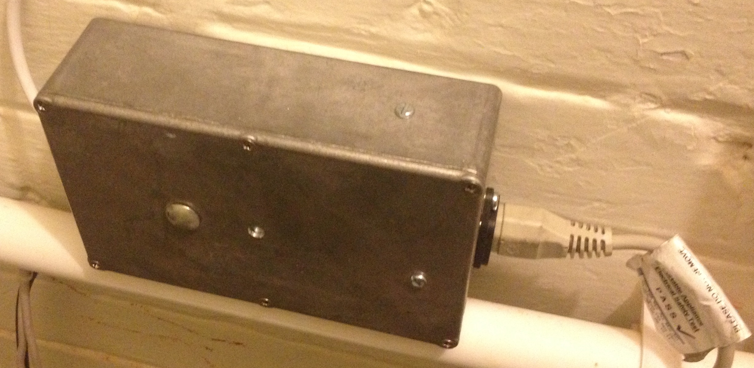
The wallbox would have, traditionally, been powered from the jukebox. To use it standalone for this project, an AC-AC transformer was required. My Wallbox required 25VAC at a maximum of 3 amps. I used a Torodial transformer, mounted with its mounting washers, in a die-cast aluminium box. It kicks out a lot of heat so the box acts as a decent enough heatsink.
The wall boxes are traditionally unearthed. This seemed like a bad idea so I attached an earth to it via one of the unit’s screws.
Interfacing with the RasPi
Steve’s circuit is floating and I managed to fairly impressively melt a RasPi by inadvertently forcing 25vAC through it via the gnd. In the end, I opted for a circuit that isolated the Pi from the Wallbox. A diagram is below:
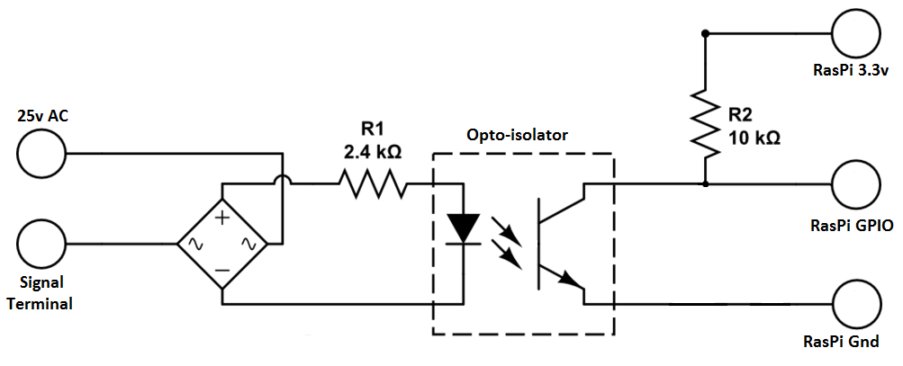
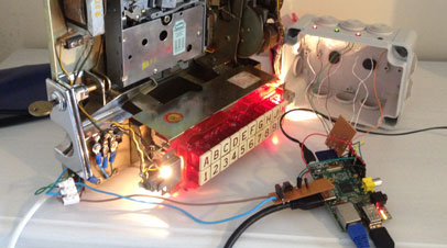
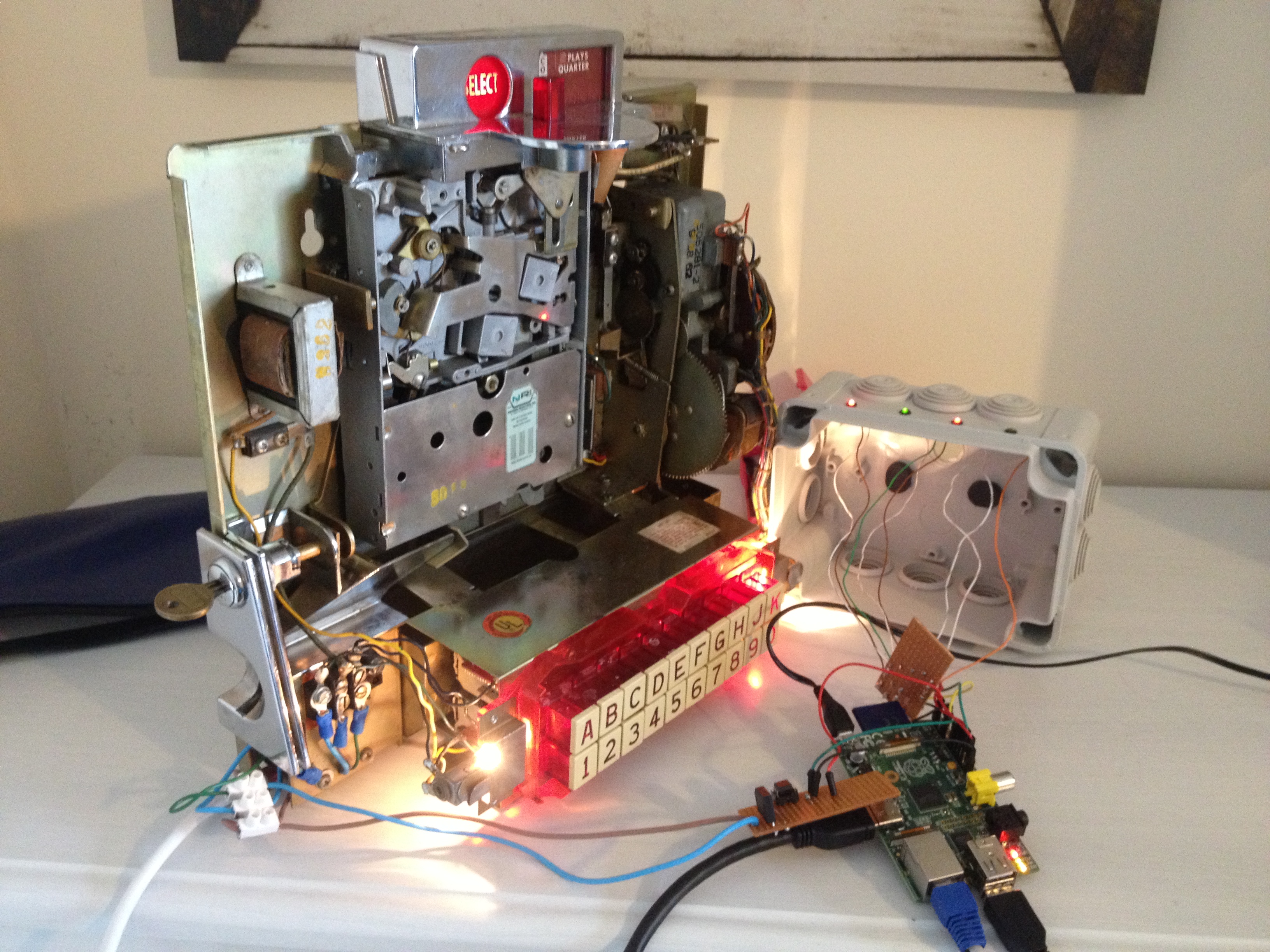
For the uninitiated, an Opto-isolatorWikipedia: An opto-isolator (also called an optocoupler, photocoupler, or optical isolator) is an electronic component that transfers electrical signals between two isolated circuits by using light.[1] Opto-isol... is an LED and a light activated transistor bundled into a single chip – it’s like a relay. In my case a DIPWikipedia: In microelectronics, a dual in-line package (DIP or DIL)[1] is an electronic component package with a rectangular housing and two parallel rows of electrical connecting pins. The package may be throug.... I used a Vishay 4N25 but anything similar to that would be fine. The left of the circuit connects to the Wallbox’s 25vAC and Signal terminals; the right connects to the RasPi. I also hooked up 4 LEDs to the Pi to provide some kind of debug output in the event of software errors.
If I were to do this circuit again, I’d add a debouncing capacitor to save having to filter out the noise/jitter from the mechanical mechanism in code. This would just be a 100nf (0.1uf) capacitor put in parallel across the output pins of the opto-isolator.
Decoding Pulses
As I eluded to above, the key combination is electrically pulsed by a rotating arm. Steve had the good fortune of having an oscilloscope to hand; I sadly didn’t. Rather, I started on the code that would decode the pulses and, initially, used it as a timer. It was clear, after filtering jitter, that the pulse train had a clear time gap in it. In Steve’s case, this gap represented a break between the letters and numbers. In my case, it represented the 20s in a base 20 numbering system.
The pulse train is sequential to represent A1 through to K0. If X represents the number of pulses before the gap and Y represents the number of pulses after the gap, X increments from 1 to 20 whilst Y stays at 1. Y then increments and X resets back to 1. The cycle repeats through to X=20, Y=4 for K0.
The maths was thus:
- Decrement both the pre and post gap counts as 0 is represented by 1 pulse
- The letter is (2 * post-gap-count) + (1 if pre-gap-count is > 10)
- If letter was worked out to be > ‘H’, add 1 as the wallbox doesn’t have an I
- The number is the pre-gap-count modulus 10 (i.e. pre-gap-count % 10)
Handling kernel level interrupts came with some problems of its own. Most notably, having to think sort-of-thread-safe when writing the code. The interrupt can… well… interrupt code processing at any time. If this is part way through a calculation, things get funky. This code is what I came up with.
Interfacing with Sonos
The Sonos “API” is a UPNP bastardization and is, frankly, horrible. PHP being my strongest language, I thought this the best way to tackle it (hence the C code’s interface with an external programme). I forked a pretty crappy Sonos class on GitHub and set about fixing/improving it. I’ve added multicast Sonos device detection and, most importantly for my requirements, Spotify support. The resulting code is on my GitHub account. Also here’s my usage of the class.
Track Cards
The Wallbox can handle 100 tracks. I had to get these into a parsable list for the Sonos code but also to print up some cards to go in the Jukebox. The Spotify API is also shocking. The best course of action I found was to use the Spotify play button generator to make an HTML page with the playlist data and then parse it with some throw-away code. Here’s the throw-away code. Don’t judge me…
Being a budding designer in my spare time, I knocked up some track card templates in Microsoft Paint. These are below:


I then used some more throw-away code to populate these with the track info. That throw-away code is here. Again, don’t judge!

I may have stumbled across a loophole in the StaplesWikipedia: Staples Inc. is an American office supply retail company headquartered in Framingham, Massachusetts. pricing system as they printed these on cards and individually cut them all out for not a lot of money.
The Finished Article
I mounted it on the wall and put the pi, circuitry, transformer, etc. on the other side of the wall to keep things clean. Picture below.
Here’s a video:
I like your article and the isolating circuit. Which Opto-Isolator did you choose? I also have the Seeburg 3w1 and am having a time trying to find the correct one.
Thanks
Thanks for your comment and e-mail. I’m not great with electronics either! It took me a while to find the right one. It’s not so much the coupler that you need to worry about but rather the resistor values.
I used a Taitron 4N25 (http://www.taitroncomponents.com/catalog/Datasheet/4N25.pdf) coupler. This one can take the 25V DC that comes from the bridge rectifier.
The first resistor value was calculated as such:
(input voltage – forward voltage) / current required = resistor value
I worked on 10mA as maximum rated current is 50mA.
(25 – 1.5) / 0.01 = 2350 ohms (rounded to 2.4KOhms).
The optocoupler apparently has a current transfer ratio of 100% at 10mA (as per Fig 2). As such, simple ohms law calculation says that:
Pi’s Output Voltage / Desired Current = Resistor Value
Thus:
3.3 / 0.00033 = 10000 ohms (10 KOhms)
The 0.33mA current here was picked based on this recommendation about not sinking more than 0.5mA into a GPIO pin. 0.33 was actually a happy coincidence of a readily available 10KOhm resistor… but it’s within bounds. http://www.mosaic-industries.com/embedded-systems/microcontroller-projects/raspberry-pi/gpio-pin-electrical-specifications
So, in summary, when picking a coupler you need to be aware of the maximum input current and the current transfer ratio at the input current that you have calculated. If the current transfer ratio is not conveniently 100% then you need to adjust the second calculation accordingly.
Phil,
This has definitely been a project. I’ve spent a good bit of time this summer working out most of the details. I have your code running and working on the Pi to interpret the key press combo. My problem is handing off the key press combo. I know nothing about programming in C#, so I set my database in Excel and wrote my program to select and play from the keypress code in Visual Basic. I have an rs232 Serial cable connecting the Raspberry Pi and my HTPC which has the Library and data base on it. Using “minicom” I am able to physically type code into the Pi and send it to the HTPC. What I need help on is how to send the key combo from your program out through Com4. You had mentioned that the programming side was your specialty and any help you could provide would be greatly appreciated. I am sure it’s just a few lines, but I keep getting errors everytime I try anything.
Thanks again. I have told several of my friends about your project and a couple of them are interested in trying this project as well once they see what my outcome is. Lol
Thanks,
Bill
Hi Phil
Really nice job. I’m delighted that you were inspired to do this after reading about my project. It’s a nice improvement to use an isolator and sorry if my floating approach was the reason for your fried Raspberry Pi (sounds like recipe!).
Best regards
Steve
Hi Phil
Im hoping this post is still ongoing
I am about to try and convert my Hyperbeam Performer Selector
Your conversion is very impressive how have you worked round the freeplay and reject ?
I also have a Sonos system and this would be unbelievable if I can achieve a result any help would be greatly appreciated
Ps
Have you any detailed photos or schematics of your stages to save me inevitable headaches Lol
Not sure what you mean by freeplay and reject :S Can you clarify?
No more photos than what’s already on here, I’m afraid
freeplay so I dont have to put coins into the box
and reject to skip a track
would I have to add push buttons features to the pi ?
I’m not too familiar with your box but free play, on mine, would be a mechanical feature of the box itself. The selection buttons aren’t activated and thus nothing moves inside the box until a coin is inserted. You’d need to bypass this mechanical mechanism.
Skip track would likely be a push button feature, yes, unless you can leverage some existing buttons on the box itself.
Thanks so here I go
will update the progress
Paul
Thanks
lets see how I get on
Paul
Hi Phil, thanks for sharing this stuff. I have realised my own project using many of your ideas. https://github.com/Abac71/Seeburg-IO
Hi Phil I’m currently converting a seeburg 3w-1 wall box and having trouble with the code. Do you by any chance still have the original code that you used.
It should all be on GitHub – https://github.com/phil-lavin/raspberry-pi-seeburg-wallbox. Happy to help if I can. What’s the problem?
I have used your site as a reference for my stand alone project using an ESP32 with MQTT to control other systems.
https://github.com/trlafleur/Tasmota_Seeburg_3WA_3W1_Decoder
I saw your work “raspberry-pi-seeburg-wallboxraspberry-pi-seeburg-wallbox” and I was very interested in what you did.
I do not have any knowledge of electrics but I do want to create something similar in that I want to interpret the signals from a number of wallboxes and send them to a computer to do a little more complex programming.
I have a couple of questions:
1. Do you have the hardware you created that I could perhaps purchase?
2. Would you be willing to arrange to offer some advice on what I am want to do?
Albert Fiscer
Happy to help if I can. I don’t have hardware for sale but I think I have some of the PCBs I printed for the second generation design – you’re welcome to have one/some if you want. Drop me an email – phil@lavin.me.uk