Intro to AC Units
An air conditioning unit isn’t a hugely complex bit of kit. Its major electrical components are a compressor and one or more fans. The compressor (unsurprisingly) compresses and, thus, cools some sort of refrigerant which then gets pumped around a series of copper pipes which are embedded inside large heat sinks. Fans draw air through the heat sinks thus cooling it and then blows it out into the room. Hot air is exhausted through a vent, usually to outside.
The compressor and fans inside an AC unit typically run at mains voltage. Capacitors are connected in parallel with these components to provide a kick-start and to control their speed. The capacitors used are typically high voltage Metalized Film Capacitors. Over some years, the capacitance of these capacitors decreases and, at some point, they will cease to hold any charge at all. As such, AC fans will slow down over time and then fail to start on their own.
AC units have some relatively simple circuitry inside to control the fans and compressor. They typically contain a basic MCU which switches relays based on the readings from some temperature sensors. Once the temperature of the compressor gets too high, it’ll be shut off and allowed to cool down. This will inevitably happen quicker, and thus the compressor will run for less time, if there is less air flow inside the unit because the fans are running slow.
AC Capacitor Replacement
Intro
My unit is a KY-32/A. It was made in 2005 and bought on eBay in circa 2012. It’s done me well over the years but its ability to cool down the room quickly has degraded over time. The fan which blows cold air out into the room eventually failed to start by itself. It would start with a gentle nudge but it didn’t spin fast enough to cool the room.

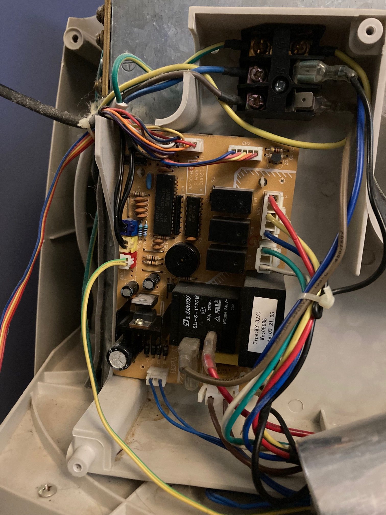
Inside the Unit
If it’s not obvious, you should unplug the unit from the mains before doing this. It’ll really hurt, if you don’t.
Opening up the unit is just a case of removing the screws that secure the cover in place. On my unit this is about 20 screws. Most of them are at the back and then there’s 6 securing the bottom of the cover.
Once inside, we can see a few key components:
- A large 30uF CBB65 capacitor for the compressor
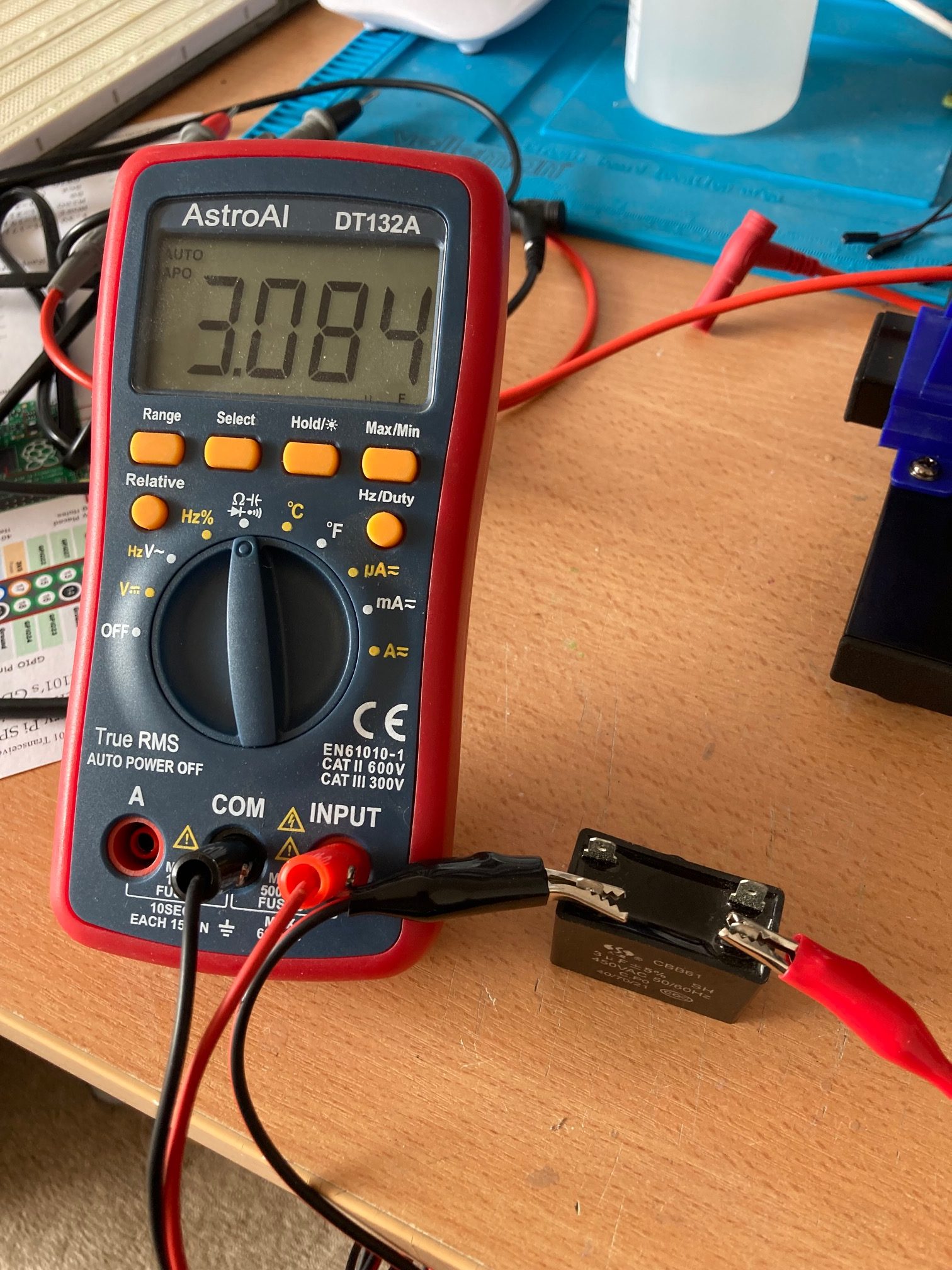
- A smaller 3uF CBB61 capacitor for the exhaust fan
- The main PCB (we’ll go into this a bit more later)
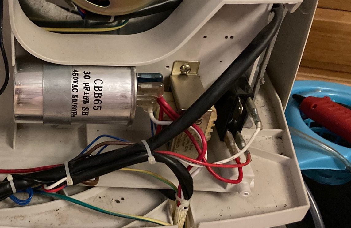
It’s a good idea to take photos of your own unit before disassembling anything so you can make sure to connect it all back up correctly.
Individual Capacitor Replacement
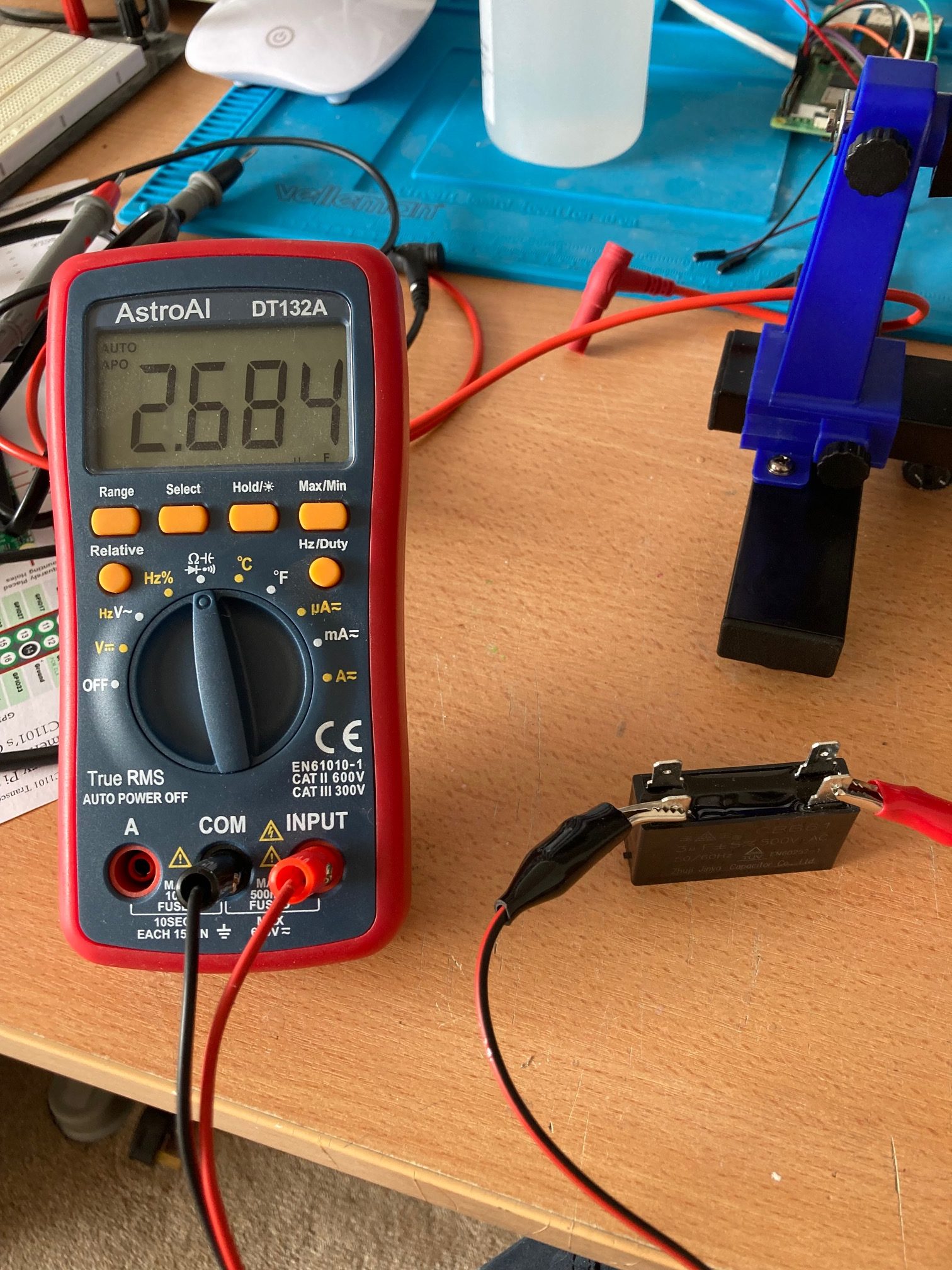
Starting first with the compressor and exhaust fan capacitors, they can be removed by removing the spade connectors and a singular screw in each. Upon testing, the CBB65 compressor capacitor it was pretty much as it should be. That said, it was leaking some oil so it seemed sensible to replace it. You can source replacements on eBay for about £7:

The CBB61 exhaust fan capacitor was well under its rated capacitance when tested so that was replaced also. Again, eBay – about £3:
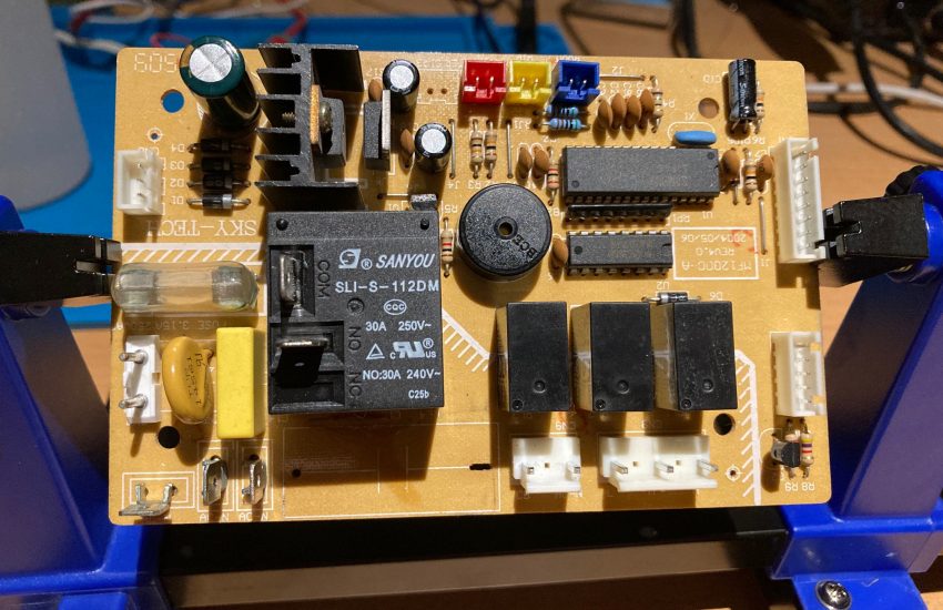
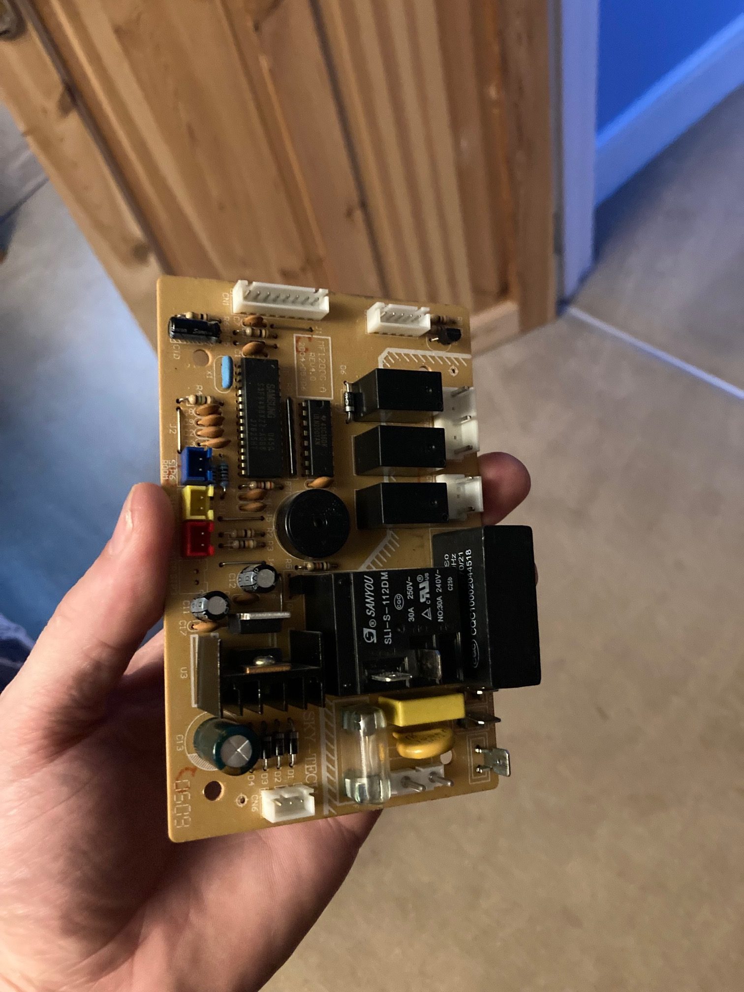
The PCB
The PCB isn’t overly complicated. As mentioned above, AC Unit PCBs are typically some shade of MCU, some temperature sensors and some relays. Mine is no different. It’s a 32 pin Samsung MCU which drives a large relay for the compressor and exhaust fan as well as 3 smaller relays for the top fan (responsible for blowing cold air into the room). 3 relays because the fan has 3 speeds.
The PCB has, soldered onto it, another CBB61 capacitor (2uF, this time) which drives the top fan. As the top fan didn’t start on its own, I suspected this was the main fault. I desoldered the capacitor from the board and tested it – it was indeed dead. Again, another eBay job to get a replacement CBB61 capacitor. This one needed to be PCB mountable so came with two long wires/pins attached.
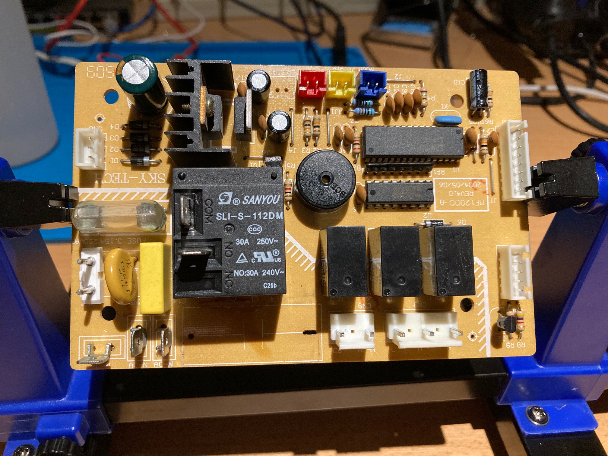
The PCB takes a 15V AC input and shoves this through a home-brew bridge rectifier (4 diodes), some smoothing capacitors, into a 12V regulator to provide the 12V DC rail, and subsequently into a 5V regulator to provide a 5V DC rail. The 1000uF 32V smoothing capacitor on the 15V side of the 12V regulator was also visibly blown. Although this didn’t cause any noticeable issues, I replaced it anyway.
Reassembly
Before reassembly, it’s a good idea to clean the heatsinks of the unit to remove built up dust. This helps air flow better. They are very fragile and the fins will bend easily. There’s a tool for that – it’s called a Fin Comb. You’ll need to get some sort of set as the spacing between fins varies wildly.
Put the unit back together in the opposite order from how you disassembled it and give it a test.
Hi i have this exact model, yes fan speed, cooling has degraded. No online manual for it yet. Love the thing but never cools below 20c thanks for making a repair guide for this, soon i will use it
i am looking for manual ky-32/a
can you help me?
This is a fantastic guide on diagnosing and replacing AC capacitors! Knowing how to safely open the unit, identify key components, and source replacements is incredibly helpful. The details on capacitor types and PCB layout are especially useful for DIY repairs. Thanks for sharing such clear, hands-on advice!