Intro
I did a post some time back about repairing a portable air conditioner unit. They’re not very complex bits of kit and, unless the compressor has broken, they’re usually very easy and cheap to repair.
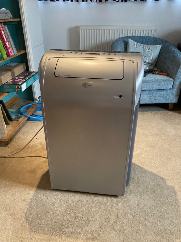
Following the 2 days of apocalyptic summer the UK had to endure in July 2022, I went looking for another portable AC unit to keep my office cool whilst working from home during the summer days. And I found a stonker! A broken AirForce GPCN12A5NK3BA, for only £20. It’s a 12,000 BTU unit with a huuuge fan that might blow the roof off, if you’re not careful 😀
Opening it Up
This unit is remarkably simple to open up. It has 2 “security” type screws on the top that you need a fork shaped screwdriver to open and then two Phillips screws on the bottom. The front panel then lifts up and slides off. The front panel has a motorised louvre vent which you simply need to unplug two connectors from to fully detach it.
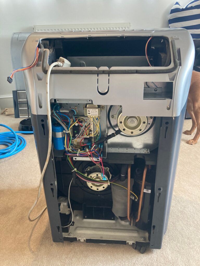
The PCB can be exposed by removing the 4 screws from the metal cover with the circuit diagram on it.
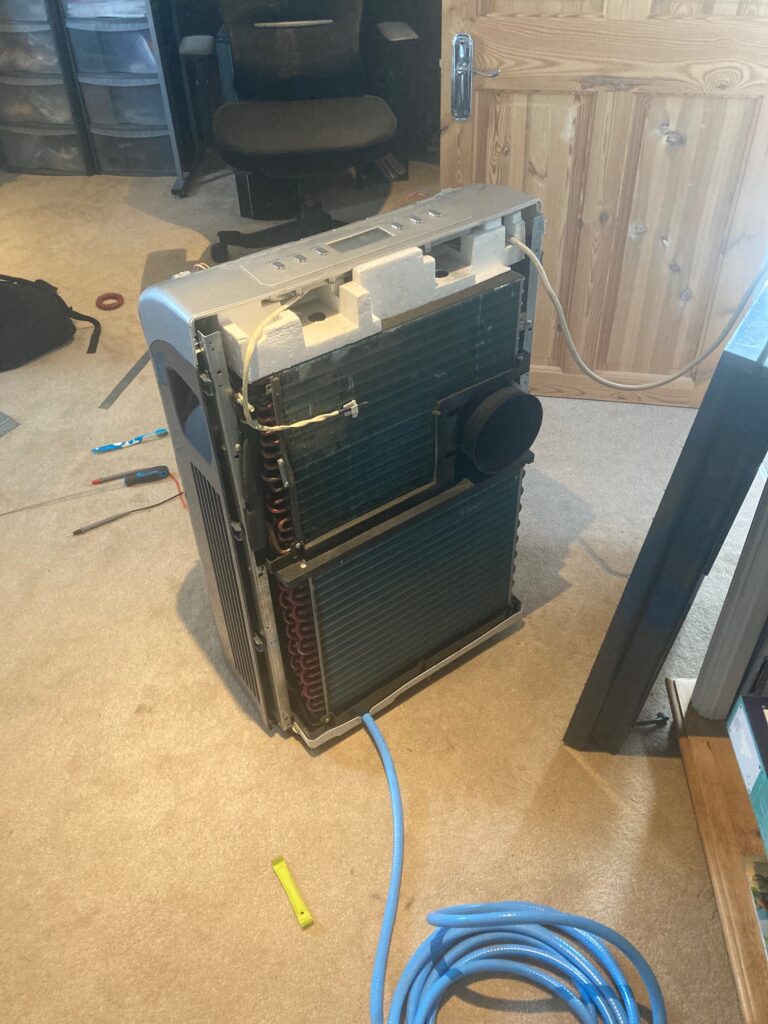
I could also see that the heatsink on the back was clogged full of dust. Removing the back was slightly more involved but it was just a case of removing a multitude of screws and lifting the cover off. It can be easily cleaned with a soft tooth brush, very careful vacuuming with a brush attachment, and a fin comb if you’re feeling fancy.
Diagnostics
When I got the unit and plugged it in, the top display turned on but none of the fans nor the compressor turned on. It was feasible that all 3 of the large capacitors which helped these things start up had died… but it felt unlikely. I tested each of the capacitors and found that only one of them was dead. This turned out to be the capacitor which powered the fan which blows cold air out into the room. Upon removing this capacitor, it was clear that it had dramatically blown as it had leaked a sort of molten plastic:
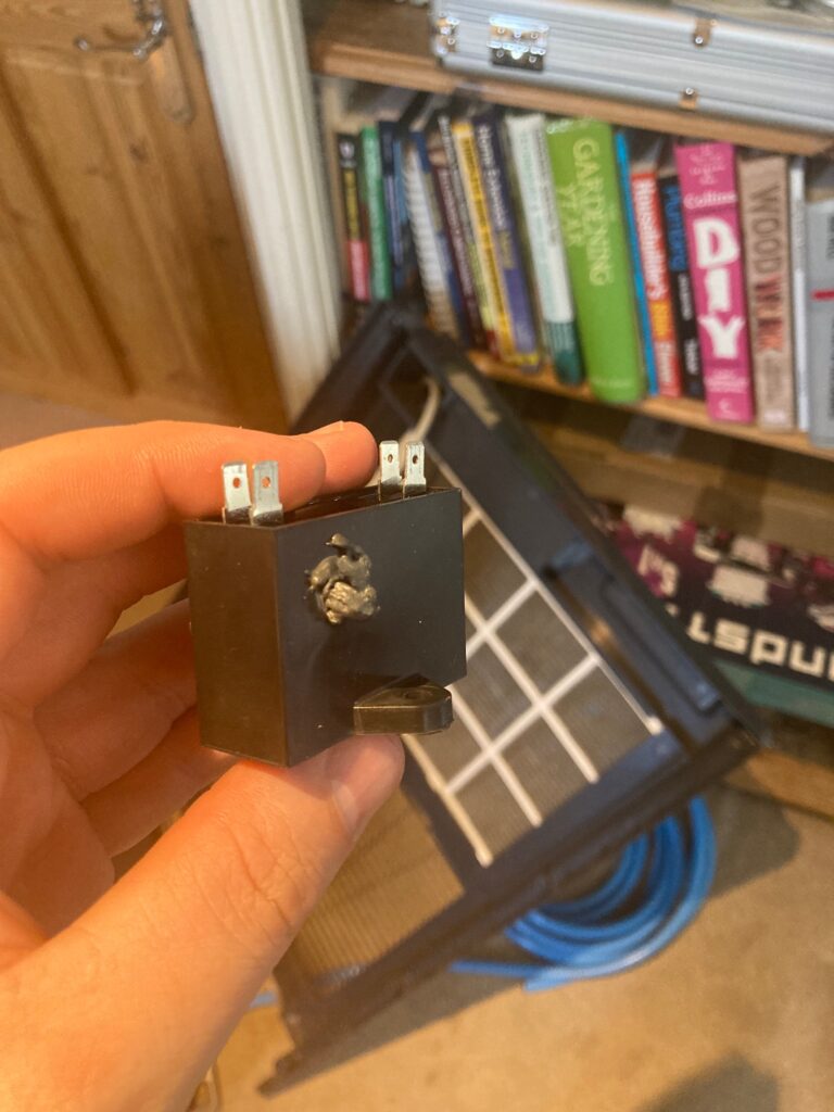
This capacitor was removed and a new one ordered but, given the others were OK, it clearly wasn’t the primary issue.
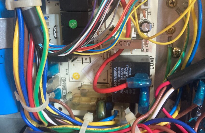
Next, I just followed the voltage on the PCB:
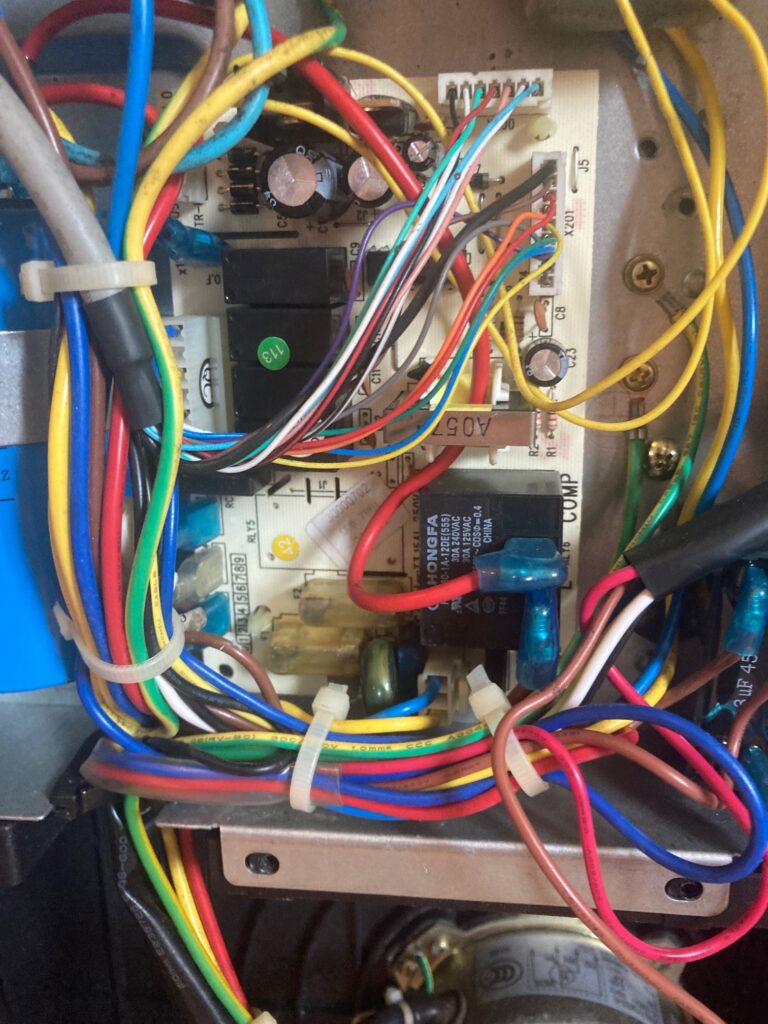
There was 240v coming into the connector block at the top of the unit so the next point to check was the two fuses you can see (covered in a yellow plastic shroud) at the bottom of the PCB. This is where I lucked out. As I poked the fuses with my multimeter, to establish the voltage, the unit beeped at me. It quickly became clear that the fuse holder contacts were dirty and weren’t making proper connection with the fuses. I removed the fuses, cleaned the contacts with a toothbrush and some Isoproyl, then put the fuses back in.
The unit now powered up, the compressor and exhaust fan ran ok. The top fan ran, slowly, if I gave it a prod. Once the new capacitor had been installed, the top fan ran perfectly on its own.
Venting Hot Air
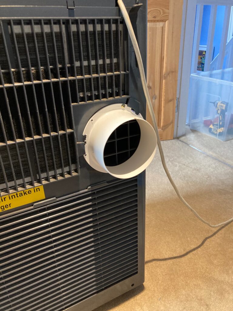
On this unit, hot air vents out the back. The unit didn’t come with the original air hose. The vent hole is a standard 125mm size. I bodged an adaptor from a cheap 125mm “flange” and screwed it on. A 125mm hose attaches to that and vents out of the window.
Hi Phil, any idea where I can find a coupler for the back of this air con unit to connect a standard exhaust hose?
I bodged an adaptor from a cheap 125mm “flange” and screwed it on. Hose just attaches to the flange with a large jubilee clip.
Hi, any ideas on where I can get a manual for this model? I search the Web and can’t find anything
hi Phil
i have the same model as this, a great unit, i have issue where when the unit is plugged in and is off the buttons will beep bethem self and and even turn on it self on.
also when the unit is on it cant be turned off via the buttons, and sometime can by remote, but the flap will close but the fan is still going so i just have to unplug it.
could offer advise on what it can be and how to fix.
Sounds like the controller. That’s the PCB at the top that the buttons are connected to. I’d start by taking it out and giving it a good clean with isoproyl
thank you so much, i did not use the unit for a few months and button issue stopped and was is working ok, lol i have a new issue now, when i switch the unit on it run fine for 10 mins with AC on and then the fuse in the plug blow, i put a new one in, but now it turns on ok but now the compressor kicks on for 2 sec or so and then goes off and will not stay on.
could this be a issue with a fuse maybe on board and do know which one to check please.
Hi Phil – Where did you source the capacitor from? My unit is working briefly before it blows the 13amp fuse
I think eBay or Amazon. Just search for the model number and find something similar.
HELLO PHIL
OUR ONE YEAR OLD POWERHOUSE AIR CONDITIONER IS NO TURNING ON JUST DOING PIP SOUND EVERY FEW SECONDS CAN IT BE REPAIRED I AM DISABLE AND 81 PLEASE HELP ME BEFORE HOT WEATHER KICKS IN
IF REPAIR IS POSSIBLE CAN YOU PLEASE RECOMMEND ANY RELIABLE REPAIRER AND IF IT IS WORTH TO DO SO
KIND REGARDS
ASHOK
Hello, I have the same unit which I have never used but picked up second hand. It used to power on but now when I switch on power, it vibrates/hums for 10 seconds then nothing, and I am unable to power on using the power button. The air intake and filter seem clean and I will whip of the covers to have a look, but any help would be greatly appreciated.
Is there a way to repair the venting fan on the Unit, it was working fine then a fan started sqealing and not the Unit doesn’t vent Air through the rear of the unit.
Have you tested the capacitor? If the fan itself is bad, you might struggle but it could well be the capacitor
i have a new issue now, when i switch the unit on it run fine for 10 mins with AC on and then the fuse in the plug blow, i put a new one in, but now it turns on ok but now the compressor kicks on for 2 sec or so and then goes off and will not stay on.
could this be a issue with a fuse maybe on board and do know which one to check please.
Hello,
If you have a multimeter, use that to test the capacitors on your board (use chatgpt or google if you need help on how to test). I found my large capacitor (the big blue one on the left) was bad it wasn’t reading any uf at all. Replaced with another 35uf CBB65 capacitor and was good to go.
My issue is with the top grill that opens and closes on power on/off .looks like the clip that holds the left side of the grill is no longer fastened and is hanging loose ,hence the grill doesn’t open and close unless you manually lift it.
You say you need a fork like screwdriver to remove the front panel can you tell me where to get one please
Thanks paul
Thank you for your post. Saved me skin. After testing mine, the samller black capacitor’s were ok (tho a little under the threshold) but my large blue capacitor was completely gone and not reading at all. Paid £10 for the whole unit as the condenser would turn on for a few seconds then turn back off but the fans would still fun. £7 new capacitor later and running perfectly.
Hi Phil,
Do you know if there air filter on the inlet that is accessible to clean please?
I have had my unit for at least 10 years or so, and I am noticing a reduction in cooling.
Aside from the filter (which you’ve now found), do check the capacitors. They are likely to have degraded over 10 years, which will result in slower fan speeds and less cooling from the compressor.
Dont worry Phil I just found it, Also I have found the manual for this AC unit.
What size is the water outlet connector on the back at the base. I can see by ur pics u have a blue hose connected upto it
It’s a standard garden hose. 12.5mm I think
Hi Phil, I’ve got the same unit , all seems OK, my temp range is 16 to 30 but only seem to be getting cold air even at 30° , is this unit a heater and ac and dehumidifier, cheers andy
Hello, Do you know where to buy an air conditioner fan turbine Just the plastic that blows out hot air?
Hello. I’m away right now but I need to order replacement capacitors. Phil – any chance you could tell me the capacitors you bought, so I can order from where I am ?
Thanks so much for your amazing article
I usually get them from eBay (cheap but slow) or Amazon (more expensive but same/next day). Regarding which one you need, they vary on each unit so you’ll have to see which one is bad then order the same part number
Hi Phil, What is the situation with the water outlet pipe a the foot of the Portable Airforce Air Con units?
Ours leaks since the pipe is open but is it supposed to be plugged?
We’ve moved a few times over the years and probably lost the proper connector.
Thanks, Andrew
I just have a standard hose pipe on mine. It drains very little water as most it evaporates when it hits the fins and is exhausted out the back. You can just drain it into a small tray
Hi,
I took this unit out of storage and when I plug it in it makes a beep sound but there is nothing coming up on the display screen and when I click any buttons, nothing happens.
Any ideas on this or where to start?
Hard to say but sounds like there’s no DC power. Could be the bridge rectifier or another part of the AC to DC circuit. A half decent electronics engineer could diagnose it. Failing that, a new PCB would likely fix it.